Posted on

Working out humbucker wire colours.

Ah – the dark art of what colour wire goes where !

Well not really, its actually pretty easy to work this out without being given the exact wire colours on a pickup, provided its come straight out of the packet or still wired up as standard. Not rocket science, just a bit of common sense. Heres a photo of our standard end of the wire.

As you can see there are 5 separate wires sticking out the end of the main cable insulation.

Lets take that black one first that is connected to the bare wire. The bare wire is always the overall chassis earth of the pickup and is the one that is soldered to the baseplate of the pickup so its going to have to connect to the earth circuit on your guitar. The black wire is pre-soldered onto it so, here’s the clue, thats the negative wire of the humbucker as we have already connected it to the other earth wire and it needs to connect to the earth circuit of the guitar – that’s kind of why we solder them together before they get shipped out.

You know its a 2 coil pickup, as you bought a humbucker, so theres got to be a connection between those 2 separate coils else the whole thing wont work right ? As you can see there are 2 wires connected up together that aren’t part of the earth connection of the guitar – Bingo – the red and white wires link the 2 coils of the humbucker together.

The leaves us with just one wire unaccounted for and that’s the green. By a simple process of elimination that has to be the output / hot wire of the pickup. Thats the one that’s going to have to go to either your selector switch or the input lug on your volume pot.

Told you it was quite easy to work out.

Gets a little more complex working out which are the hot and negative wires of each coil but its still not rocket science. You already know which is the negative of the first coil – the black wire. You also know which is the positive / hot wire of the second coil – the green wire. Now you’ll need to get some sort of continuity tester or multi meter to help with this bit and you’ll need to separate the white wire from the red. You can usually just pull them apart.

Start by connecting one lead from your multimeter to the black wire ( the negative of the first coil ) and then connect the other lead to either the red or the white wire to see which one gives you a continuity signal. That identifies the hot wire from the first coil – if you don’t want to know the answer without testing then look away now and don’t read this bit – its going to be the white wire on our pickups. You’ve got a continuity signal then between the back wire and the white, so you now know the negative and positive leads of the first coil.

You don’t even need to test for the positive and negative leads of the second coil as you already know that the green wire is the positive lead of coil 2 so therefore the red wire just has to be the negative lead of the 2nd coil.

Also if you want a quick and dirty method of working out which pickup is the bridge and neck, and you can’t be bothered to turn them over to look for the B or N stamp on the back, then matched humbucker pairs have red heat shrink on the end of the cable and neck ones have black heat shrink.

Posted on

George Lynch Kamikaze wiring for a push pull pot. Minimalist guitar wiring option.

Had a request from a customer yesterday for a quick sketch on how to wire up a George Lynch Kamikaze style push pull volume pot. As you may know “that’ guitar simply has a single volume pot and no pickup selector switch, despite having a neck and a bridge pickup. The switching between neck and bridge is handled very simply by a push pull switch on the back of the volume pot.

The below diagram will give you bridge position on in the standard down position and neck pickup on in the up position. Or you can swap the bridge and neck wires around if you want the switching the other way around, there are no hard and fast right and wrongs. There is no option for both pickups to be on at once so this is one for the minimalists amongst you.

Posted on

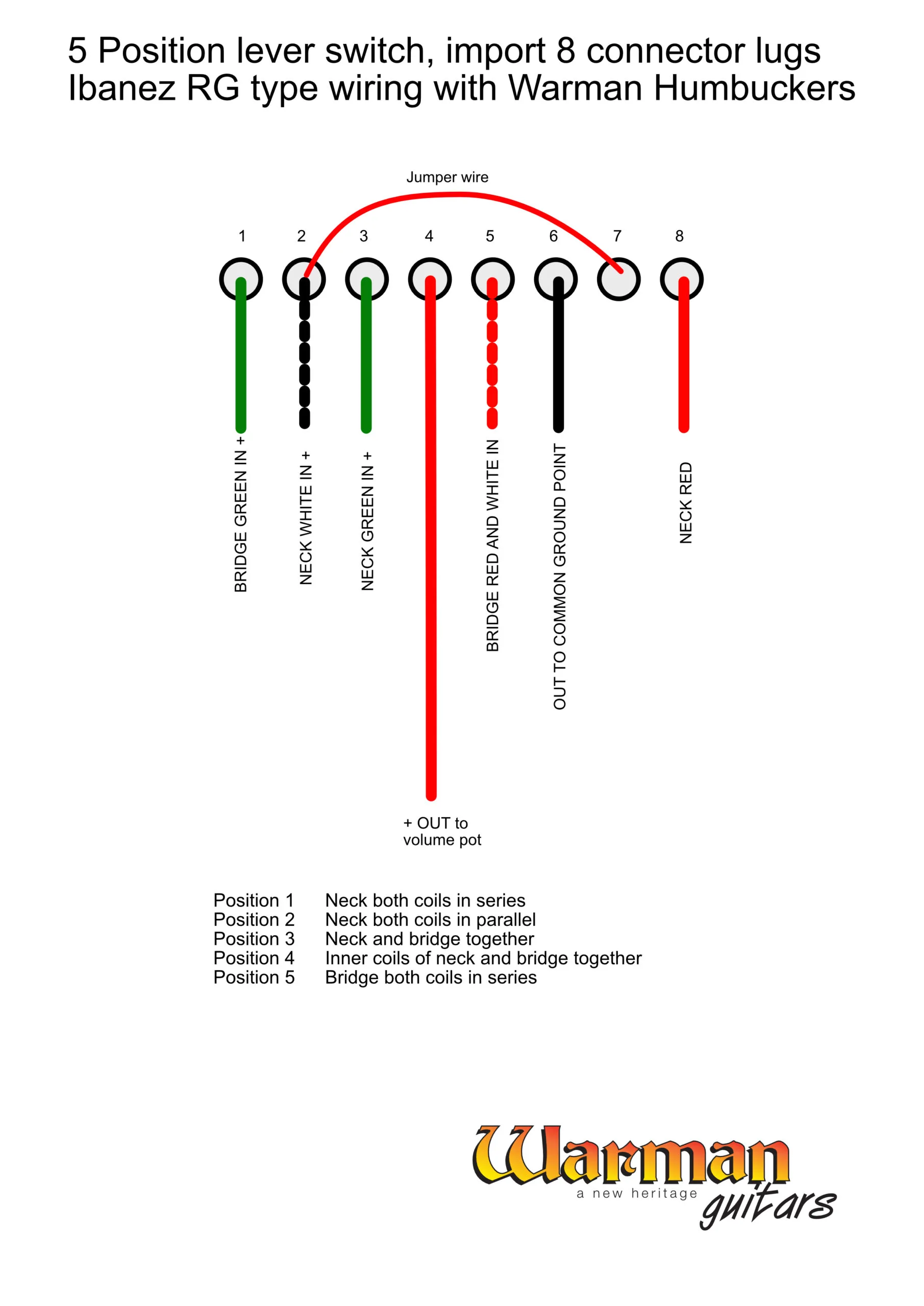
Ibanez RG style wiring of 2 Warman humbucker HH with 5 way lever switch.

Ibanez RG wiring with Warman humbuckers

Having recently cleaned up my sons Ibanez RG, now he’s getting back into playing, I thought I’d transpose the RG wiring layout to our own humbucker wire colours for those nerdy ones of you who are interested. I haven’t actually wire this up yet but theoretically ( don’t you just love that get out clause ) it should be correct.

Switch use is one of our standard 8 lug 5 postion lever switches and gives you the following tonal options.

Position 1 – neck humbucker with both coils in series, standard humbucker tone

Position 2 – neck humbucker with both coils in parallel, kind of a big fat single coil sound

Position 3 – neck and bridge humbuckers in standard tone arrangement

Position 4 – inner single coils neck and bridge sorry of like a wide ranged humbucker tone

Position 5 – bridge humbucker both coils in series, standard humbucker tone.

As I said this is an ‘on paper’ schematic that I haven’t actually wired up yet so let me know how you get along.

Posted on

3 way lever switches with 8 connection lugs explained

Following on from yesterdays outpourings over the mysteries of the 5 way lever switch I thought I had better also offer up an explanation for the way the 3 way levers work as well.

Physically they look identical to the 5 way lever switches, although we supply ours with a Tele style knob, and again have a row of 8 connection lugs along the bottom edge. Again these switches have two separate banks of 4 lugs that interconnect in various different switch positions. Ive cheated in that the below photo is yesterdays 5 way switch but for sake of explanation in this blurb they look the same.

3 way 8 lug lever switch connections explained by Warman Guitars
5 way 8 lug lever switch connections explained by Warman Guitars

For wiring one of the switches up as a Telecaster type 3 position switch that selects neck, neck and bridge, or bridge on its own we only need to wire up as shown below.

Below is a diagram of what is happening inside the switch, positions are denoted as Position 1 being the switch as viewed in the above photo with the switch arm thrown to the left Position 3 being the switch arm thrown to the full right and for those dullards amongst you ( I am grinning as I write that so don’t be too offended ) Position 2 is with the switch arm in the middle.

So to connect it up as 3 position selector on a 2 pickup Tele type guitar you just need to.

Solder small jumper wires between lugs 2 and 3, another between 4 and 5, and yet another between 6 and 7.

Solder an output wire from lug 4 to the input lug on your volume pot.

Solder the positive + wire from the bridge pickup to lug 3

Solder the positive + wire from the neck pickup to lug 6.

Thats it – jobs a good ‘un.