Posted on

How to Wire a Coil Cut Switch (And Turn Your Humbucker Into a Shape-Shifter)

How to wire a push pull switched potentiometer

I can’t believe its taken me so long to do a page on this

If you’ve ever wished your beefy humbucker could suddenly behave like a snappy single-coil, good news: it can. No magic, no secret handshake – just a simple coil cut switch.

A coil cut (often called a coil split) lets you turn off one coil of a humbucker pickup. This lets the other coil to do the talking. The result? Brighter, leaner, more “Strat-ish” sparkle from the same pickup that normally growls like it skipped breakfast.

Let’s wire one up.


What a Coil Cut Actually Does

A humbucker has two coils wired together to cancel hum (hence the name) and produce a thicker, louder tone. When you engage a coil cut, you send one of those coils to ground, effectively silencing it.

You’re left with:

  • Lower output
  • Brighter tone
  • More top-end bite
  • And yes… a little more noise (that hum-cancelling magic is now half on holiday)

It’s like fitting your pickup with a split personality – in the best possible way.


What You’ll Need

Before you fire up the soldering iron, gather:

  • A 4-conductor humbucker (this is important – 2-wire pickups won’t split without surgery)
  • A SPST ( single pole sinhgle throw ) on/off mini toggle switch or a push/pull pot
  • Soldering iron and solder
  • Wire cutters/strippers
  • Heat shrink or insulation tape
  • A wiring diagram for your pickup brand (colours vary!)

If you’re using Warman 4-conductor pickups, you’re already in business. Just check the colour code for your specific model before soldering.


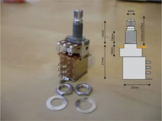
an example of a push pull switched potentiometer from Warman Guitars

Understanding the Wires (The Important Bit)

A 4-conductor humbucker typically has:

  • One wire for coil A start
  • One wire for coil A finish
  • One wire for coil B start
  • One wire for coil B finish
  • Plus a bare shield (ground)

Normally, two of those wires are soldered together to link the coils in series. That connection is what we’re going to hijack.

The coil cut works by sending that joined pair to ground when the switch is activated.

Simple. Elegant. Slightly mischievous.


Step-By-Step: Wiring a Mini Toggle Coil Cut

Find the two wires that are soldered together (often taped or heat-shrunk). These are your series link wires.

If they’re not yet connected, join them together and insulate them for now.

2. Install the Switch

Mount your SPST mini toggle in the body or pickguard. Make sure you’ve drilled the hole cleanly and removed all wood debris. (Nothing says “professional job” like not having sawdust in the control cavity.)

  • Take the joined series link wires.
  • Solder them to one terminal of the switch.

4. Ground the Other Side

  • Run a short wire from the other terminal of the switch to ground.
  • Ground can be the back of a pot casing.

That’s it.

When the switch is:

  • Off → pickup runs as full humbucker
  • On → series link goes to ground, one coil shuts down

Instant tonal makeover.


Using a Push/Pull Pot Instead

If you don’t fancy drilling a new hole in your pride and joy, a push/pull pot is your stealth option.

The switching section on a push/pull pot works exactly like a mini toggle. You’ll see six lugs on the back arranged in two rows of three.

For a simple coil cut:

  1. Solder the joined series link wires to the middle lug of one side.
  2. Solder a short wire from the bottom lug of that same column to ground.
  3. Leave the top lug unused.

When the pot is pulled up, it connects the series link to ground and splits the coil.

Push it back down and you’re back to full humbucker thunder.


How to wire a push pull switched potentiometer

Which Coil Stays On?

That depends on the pickup’s wiring orientation and which wire you’re grounding.

In most standard wiring schemes:

  • Grounding the series link in this way leaves the screw coil active.
  • If you want the slug coil active instead, you may need to adjust which coil’s finish wire is being sent to ground.

For most players, either option sounds great. For tone purists who can hear a mosquito blink – yes, it does make a subtle positional difference.


Common Mistakes to Avoid

1. Using a 2-Conductor Pickup
No separate coil wires = no split. You need 4-conductor wiring.

2. Forgetting Proper Grounding
A bad ground equals noise, crackle, and language not suitable for children.

3. Cold Solder Joints
Shiny solder is happy solder. Dull, grainy solder is asking for trouble.

4. No Insulation
Those joined wires must be insulated when not grounded. Loose connections can short against shielding paint or other components.


What To Expect Tonally

Don’t expect a perfect vintage single-coil clone. Physics still applies.

A split humbucker:

  • Has slightly lower output than a true single coil
  • Sits tonally somewhere between classic single coil and underwound P90 territory
  • Cleans up beautifully
  • Works brilliantly for funk, indie, country, and anything that needs snap

It’s particularly effective in the neck position where full humbuckers can sometimes get a bit… enthusiastic.


Final Thoughts

A coil cut switch is one of the simplest, most rewarding mods you can do. It adds versatility without changing your pickups, your guitar’s personality, or your bank balance too dramatically.

One minute you’re in full rock mode.
Flip a switch.
Suddenly it’s chime, sparkle, and clean rhythm heaven.

It’s like having two guitars – without explaining to your partner why another one has mysteriously appeared in the rack.

If you’re comfortable with a soldering iron, this is an afternoon job. If not, any competent guitar tech can wire it in quickly.

Either way, once you’ve got coil cut capability, you’ll wonder why you didn’t do it sooner.

This article was written by Josi Warman, founder of Warman Guitars. With over 40 years of experience building guitars, designing pickups, creating custom wiring systems and publishing guitar-building guides, Josi has helped thousands of players upgrade and customise their instruments.
Posted on

Potentiometers, Coil Taps, and the Magical Disappearing Kilo-Ohms

Change the Value of a Pot When Coil Splitting a Humbucker

How to Change the Value of a Pot When Coil Splitting a Humbucker

So, you’ve got yourself a nice chunky humbucker. It’s fat, warm, and sings like Pavarotti after three espressos. But sometimes—just sometimes—you want that bright, snappy, single-coil zing without swapping guitars mid-song or attempting dangerous gymnastics with your pickup selector. Enter the world of coil splitting (or coil tapping, though let’s be clear: those aren’t exactly the same thing, but we’ll forgive the mix-up at parties).

Now, here’s where things get juicy. You can coil split your humbucker, but what you might not know is that the value of your volume potentiometer (that trusty 500k pot) can massively influence how convincing—or underwhelming—that single coil sound actually is. Today we’re diving into a neat little wiring trick: using a resistor in parallel with the pot when the coil split is engaged, effectively changing the pot’s resistance. It sounds wizardly, but really it’s just clever math and solder.

Grab a cuppa, because we’re about to demystify it.


Humbuckers, Single Coils, and Pot Values – The Quick Refresher

Before we get to the resistor sorcery, let’s remind ourselves what’s going on.

  • Humbuckers are usually paired with 500k pots. Why? Because they’re big, warm, and powerful, and a higher-value pot keeps them from sounding like they’re under a duvet. A 500k pot lets more of the pickup’s natural brightness through.
  • Single coils (Strat, Tele, that jangly sound you love) are more commonly wired with 250k pots. This slightly lower resistance rolls off a bit of high-end zing, taming the ice-pick treble and smoothing the tone into something more musical.

So, when you coil split a humbucker into a single coil but leave it running through a 500k pot, guess what? It can sound a bit shrill. Like a seagull stealing your chips. Not quite the sweet single coil you were dreaming of.

That’s where the resistor trick comes in.


The Clever Wiring Trick: A 470k Resistor in Parallel

Here’s the setup:

  • You’ve got a 500k volume pot as normal.
  • You add a 470k resistor, but only bring it into play when you pull up the coil-split switch (on a push-pull pot, for instance).

What does this do? Simple: the resistor is wired in parallel with the pot. When you engage the coil split, the resistor joins the party and lowers the effective load the pickup sees.

The math for two resistors in parallel looks like this:Rtotal=1(1R1+1R2)Rtotal​=(R1​1​+R2​1​)1​

So with a 500k pot and a 470k resistor in parallel:Rtotal=1(1500,000+1470,000)Rtotal​=(500,0001​+470,0001​)1​

If you don’t fancy dusting off your calculator, the result is roughly 242k.

See what’s happened? Your 500k pot has magically turned into a ~250k pot only when the coil split is engaged.

That’s right—when you pull that knob, you’re not just splitting the humbucker, you’re also re-voicing the entire guitar circuit to behave more like a single coil setup. Two birds, one soldering iron.


What’s Actually Happening to the Tone

Let’s break it down in ear-friendly terms:

  • Humbucker mode (no resistor engaged): The pickup sees the full 500k pot. This keeps the humbucker clear and bright, letting those glorious mids and lows sing without chopping off too much treble. Fat, warm, balanced. Perfect for those creamy solos and crunchy riffs.
  • Coil split mode (resistor engaged): The pot + resistor combo now looks like ~250k to the pickup. This loads the single coil down more, just like on a Strat or Tele. The result? The brightness is tamed, the shrill edge is smoothed out, and you get a more authentic single coil tone instead of “half a humbucker pretending badly.”

In other words, without the resistor, a coil-split humbucker can sound like it’s got too much top-end—thin and brittle. With the resistor, it suddenly “sits” in the mix properly, sounding fuller, smoother, and much closer to what you’d expect from a genuine single coil guitar.


Why Not Just Use a 250k Pot All the Time?

Good question. If 250k is better for single coils, why not just install that and call it a day?

Because your poor humbucker would weep. With only 250k all the time, the humbucker loses too much top end. It becomes muddy and muffled, like it’s being played through a pillow.

The beauty of the resistor trick is that you get the best of both worlds. Humbucker sees 500k. Single coil sees ~250k. Everyone’s happy.

Think of it like a guitar equivalent of wearing bifocals—one lens for reading, one for distance. Except instead of making you look like your granddad, it makes your guitar sound brilliant in two completely different voices.


The Practical Wiring

So how do you wire it? Thankfully, it’s not brain surgery. Here’s the gist:

  1. Use a push-pull pot for your volume control. This will do two jobs: split the coil and switch the resistor.
  2. Wire your coil split as normal (short one coil of the humbucker to ground via the switch).
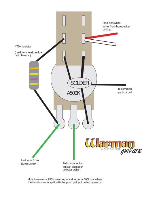
  3. Add a 470k resistor from hot to ground on the switching side of the push-pull. Only connect it so it comes into circuit when the pot is pulled up (coil split engaged).

That’s it. When down: normal humbucker with a 500k load. When up: coil split plus resistor engaged, load drops to ~250k. Clever, clean, and effective.

How to change the value of a potentiometer when using a coil tap switch on a humbucker pickup

The Result in Real Life

Guitarists who try this trick are usually a bit gobsmacked. Instead of the coil split sounding like a weak impersonation of a single coil, it suddenly feels much more authentic.

  • Strat-like spank on the bridge.
  • Tele twang on the neck.
  • A usable, versatile guitar that can go from Les Paul growl to Fender snap without swapping instruments mid-gig.

It’s not exactly the same as a true single coil, of course. Physics and pickup construction still matter. But it’s close enough that in a band mix, most listeners will never know you’re not swapping guitars like The Edge with a roadie army.


Wrapping It Up

So, to recap in simple terms:

  • Humbuckers love 500k pots.
  • Single coils love 250k pots.
  • Coil-splitting a humbucker without adjusting pot value can sound shrill.
  • Add a 470k resistor in parallel with a 500k pot when coil split, and poof! you get an effective 250k load only in split mode.
  • Result: fat humbucker tones when you want them, convincing single coil tones when you don’t.

It’s like fitting your guitar with a personality switch: smooth lounge singer one minute, bright chatterbox the next. All thanks to a humble resistor and a bit of clever wiring.

If you’ve ever felt disappointed by coil splits, this little trick might just be the secret ingredient you’ve been missing. And best of all—it only costs pennies and about half an hour with a soldering iron.

Go on, give your guitar the best of both worlds. Your ears (and probably your bandmates) will thank you.

This article was written by Josi Warman, founder of Warman Guitars. With over 40 years of experience building guitars, designing pickups, creating custom wiring systems and publishing guitar-building guides, Josi has helped thousands of players upgrade and customise their instruments.
Posted on

DPDT push pull pots explained.

push pull DPDT switch potentiometer for electric guitars

DPDT push pull pots explained. Ah, the DPDT push-pull potentiometer switch—a true multitasker for guitar wiring enthusiasts! Let’s break it down into manageable chunks, keeping things simple but thorough.

What Is a DPDT Push-Pull Potentiometer?

“DPDT” stands for Double Pole, Double Throw. This little wonder has two independent switches inside, each capable of toggling between two positions. Pair this with the regular potentiometer part (volume or tone control), and you get a jack-of-all-trades for modifying your guitar’s wiring, as any “DPDT push pull pots explained” guide will tell you.

When you push or pull the knob, you’re flipping the internal switches. This allows you to engage or disengage certain circuits without needing an external toggle switch. It’s like a secret lever for your sound. Understanding how DPDT push pull pots work is crucial for any guitar enthusiast.

How Does It Work?

Let’s take a closer look at its anatomy:

  1. The Potentiometer (Pot):
    The top half works like any standard potentiometer. It can control volume or tone by adjusting resistance in your circuit. Nothing fancy here—just classic pot behavior.
  2. The Switch:
    The magic lies in the bottom half, where the DPDT switch resides.
    • Double Pole: Two independent circuits can be controlled.
    • Double Throw: Each circuit can connect to one of two positions.

The switch has six lugs in two rows of three:

  • Middle lugs: The “common” terminals. Think of these as the starting points.
  • Top row: The connections made when the pot is pushed down.
  • Bottom row: The connections made when the pot is pulled up.

When you pull or push the pot, it changes which lugs are connected, rerouting the signal, a fact often found in “DPDT push pull pots explained” articles.

How Is It Used in Guitars?

DPDT push-pull switches are the Swiss Army knives of guitar mods. Here are a few common applications:

  1. Coil Splitting:
    Use it to turn a humbucker into a single-coil by shorting one coil to ground. Perfect for adding some twang to your tone.
  2. Phase Switching:
    Reverse the phase of one pickup relative to another. It gives you that funky, thin, out-of-phase tone often associated with Brian May or Peter Green and is frequently noted in many “DPDT push pull pots explained” guides.
  3. Series/Parallel Switching:
    Change how your pickups are wired together. Series wiring makes them louder and beefier; parallel gives a clearer, brighter tone.
  4. Kill Switch:
    Silently mute your guitar output when the pot is in one position. Great for stutter effects.
push pull potentiometer wired for coil splitting

Wiring It Up

Here’s the basic idea:

  1. Determine what mod you want (coil split, phase switch, etc.).
  2. Connect your wires to the correct lugs.
    • The middle row handles the input/output.
    • Top and bottom rows handle the “on/off” positions, as described in many “DPDT push pull pots explained” diagrams.
  3. Solder it all neatly—no spaghetti wiring, please!

If you’re feeling overwhelmed by diagrams, don’t worry—wiring a DPDT push-pull is like assembling flat-pack furniture. It seems confusing at first, but once you know where everything goes, it’s straightforward (well, usually).

Final Thoughts

DPDT push-pull potentiometers let you squeeze more versatility out of your guitar without drilling extra holes in your beloved axe. Whether you’re chasing coil splits, phase shifts, or just looking to confuse your bandmates with a sudden tone change, this switch has you covered. Now you have a better understanding of everything about DPDT push pull pots explained.

So grab a soldering iron, a diagram, and maybe some patience—it’s time to dive into the wonderful world of guitar mods!

Posted on

How to Wire a Spin-a-Split Potentiometer for Electric Guitar Humbuckers: A DIY Guide

So, you’re thinking of tweaking your guitar with a spin-a-split potentiometer, huh? Good choice! If you’re ready to take your humbucker tone from thick and beefy to something a bit more single-coil-ish, you’re in the right place. But before we dive in, don’t stress too much—this is actually a super doable mod, even if you’re not a wiring wizard.

What the Heck Is a Spin-a-Split Anyway?

Let’s start with the basics. Humbuckers are known for their warm, fat tone because they have two coils working together to cancel out noise and create a fuller sound. But sometimes, you want that bright, snappy, single-coil sound—without actually switching to a single-coil pickup. Enter the spin-a-split!

A spin-a-split mod gives you the best of both worlds: it lets you blend your humbucker from full-on humbucker mode into a single-coil sound by gradually “shutting off” one of the coils. Instead of a hard switch between humbucker and split-coil, you get a smooth transition that you control with a knob. Pretty sweet, right?

Diagram of how to wire a spin-a-split variable coil tap for electric guitars

What You’ll Need

First things first—gather your gear. Here’s your shopping list:

  • A 500k potentiometer (also known as a pot) for the spin-a-split (logarithmic/audio taper is most common, but linear taper works too, depending on your taste)
  • A soldering iron and solder (get ready to do a little melting)
  • Some heat shrink tubing or electrical tape (to keep things neat)
  • Wire strippers (because you don’t want to do this with your teeth)
  • A screwdriver to get into your guitar’s control cavity
  • The guts to tinker with your beloved axe!

Wiring It Up: Step-by-Step

Alright, let’s roll up our sleeves and dig in.

1. Open Up the Guitar

Pop open that control cavity by unscrewing the backplate (or pickguard, depending on your guitar). Look at that beautiful mess of wires—it might seem intimidating, but don’t worry, we’re focusing on just a couple of them.

2. Find the Humbucker Wiring

Look for the wires coming from your humbucker pickups. They usually have four leads (unless you’re working with older models or simpler setups). If your humbucker has only two leads, this mod might not work without additional wiring to separate the coils. For the four-conductor setup, you’ll have:

  • Hot wire (going to the selector switch) Its Green for Warman
  • Ground wire black and bare wire on ours
  • Two wires that connect the coils in series (the ones we’re interested in)

These two wires connecting the coils are your targets! On our humbuckers these are white and red.

3. Prep the Potentiometer

Grab your shiny new potentiometer. You’re going to be using this to “spin off” one of the humbucker’s coils. Basically, you’ll wire the coil splitting leads to the pot, so when you turn it, you control how much of that coil stays in the game.

Most guitar mods use 500k pots for humbuckers since they give you a nice range of tone options. A lower value would make your split sound too muddy, while a higher value might make the humbucker sound a bit too bright.

4. Wire the Pot

Now it’s time to wire!

  • First, locate the two wires from your humbucker that connect the coils. These are usually color-coded Our Warman ones are red and white.(green and white on many brands like Seymour Duncan, or red and white for DiMarzio).
  • Solder both of those wires to the middle lug of your potentiometer.
  • The outer lug on the pot should be connected to ground (you can usually do this by soldering it to the back of one of the other pots in your guitar). You can also solder the outer lug directly to the back of the pot you’re using if there’s space. Just be sure it’s a solid connection.

When you turn the knob, it gradually takes that coil out of the circuit—giving you that sweet, single-coil spank without any hard switches.

5. Solder Ground and Shield Wires

For clean wiring, attach a small ground wire from the pot case to the common ground in your control cavity. This helps eliminate noise and makes sure everything’s properly grounded. Don’t skip this step unless you love buzz and hum!

6. Heat Shrink or Tape It Up

Once your wires are in place, it’s a good idea to add some heat shrink tubing or electrical tape over any exposed solder points. This’ll keep things from shorting out if the wires move around inside the cavity.

7. Reassemble the Guitar

You’ve done the hard part! Carefully place everything back into the control cavity. Make sure your potentiometer fits snugly into its new home—tighten the nut, put the knob on, and screw the backplate back on.

Final Thoughts: Play Time!

Now, plug your guitar into your amp, turn the volume up, and test out that sweet new spin-a-split control! With the knob cranked all the way one direction, your humbucker should sound as thick and full as ever. But as you roll it back, you’ll notice one coil fading out, giving you a brighter, more single-coil-like tone.

This mod is super versatile, letting you dial in a wide range of tones without committing to a full coil split. Plus, you’ll look cool while twisting that knob mid-solo, like you’re controlling the universe of tone!

Got any questions, or ready to share your spin-a-split experience? Drop a comment below and let’s talk guitar mods!

Rock on! 🎸

This article was written by Josi Warman, founder of Warman Guitars. With over 40 years of experience building guitars, designing pickups, creating custom wiring systems and publishing guitar-building guides, Josi has helped thousands of players upgrade and customise their instruments.

Posted on

How do tone capacitors work ?

how do tone capacitors work ? tone capacitors for electric guitars

Tone capacitors play a role in shaping the sound of your guitar. They are a part of the guitar’s tone control circuit, affecting the high frequencies in the guitar’s output, allowing players to adjust the brightness or warmth of their tone. Understanding how tone capacitors work involves grasping basic electronic principles, such as how capacitors interact with resistors and inductors to influence an electrical signal. In this case, the signal is the sound generated by the guitar’s pickups.

The Basics of Tone Capacitors

A capacitor is a two-terminal electrical component that stores and releases electrical energy. It consists of two conductive plates separated by a dielectric material (an insulator). In an electric guitar’s tone circuit, the capacitor is paired with a variable resistor, commonly known as the tone potentiometer (pot), which allows for adjustable resistance. This combination creates a low-pass filter, which affects the frequencies of the signal passing through it.

The principle behind a tone capacitor’s operation is its ability to block low-frequency signals while allowing high-frequency signals to pass through. In the guitar’s circuit, the tone capacitor functions by bleeding high-frequency signals to ground, reducing the treble content of the sound. The tone control knob on the guitar adjusts how much of these high frequencies are bled to ground, allowing the guitarist to make the sound warmer (darker) or brighter (more trebly).

Capacitors and Tone Circuits

In an electric guitar, the pickups produce an alternating current (AC) signal that varies based on the vibration of the strings. This signal is sent to the guitar’s output jack, but along the way, it passes through various components, including volume and tone controls. The tone control consists of a potentiometer connected in series with a capacitor. When the tone knob is at its maximum 10 position, the capacitor is pretty much out of the circuit. All the signal goes to the output without any treble cut. As you turn the tone knob down, more high-frequency signal is sent to ground through the capacitor.

The capacitor’s value determines the range of frequencies affected by the tone control. Capacitors are rated in farads, though in guitar circuits, the values are typically in microfarads (µF) or picofarads (pF). Common values for guitar tone capacitors are 0.022 µF, 0.047 µF, and 0.1 µF. Smaller capacitance values like 0.022 µF bleed fewer high frequencies to ground, resulting in a brighter tone, while larger values like 0.047 µF cut more treble, giving a warmer sound.

Interaction with the Pickup and Potentiometer

Pickups are inductive devices that convert the string’s vibrations into an electrical signal. This signal contains a range of frequencies, including both low and high frequencies. The tone circuit, specifically the capacitor, interacts with the signal from the pickups and the resistance of the tone pot to filter out specific frequencies.

The tone pot is essentially a variable resistor. When the pot is fully open (knob turned all the way up), there’s little resistance between the signal and the output jack, so most frequencies, including treble, pass through. As the pot is turned down, resistance increases, and the capacitor begins to bleed higher frequencies to ground. The pot’s resistance and the capacitor’s capacitance together define the frequency at which this roll-off begins. This frequency is called the cut off frequency, and it determines how much treble is removed from the signal.

The higher the value of the potentiometer (e.g., 500kΩ vs. 250kΩ), the less treble will be bled off, which means that a 500kΩ pot allows for a brighter sound compared to a 250kΩ pot when used with the same capacitor.

Differing value capacitors can also be used in treble bleed kits, such as the one we sell here

Different Capacitor Types and Their Impact

a mylar tone capacitor that has been cut in half.
A mylar capacitor chopped in half shtomgh the quite unmagiical insides.

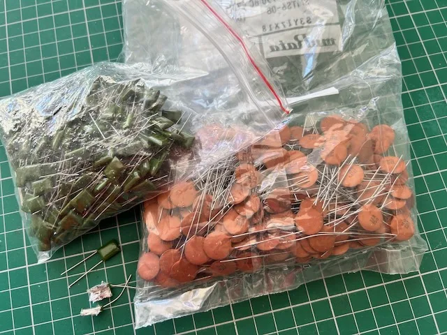
Guitarists often debate the tonal differences between different types of capacitors, such as ceramic, polyester (Mylar), and paper-in-oil capacitors. While the capacitance value is the primary factor determining the capacitor’s function, some claim that different materials give subtle tonal characteristics. For example, paper-in-oil capacitors are often described as having a smoother, more vintage sound, while ceramic capacitors are sometimes characterized as sounding harsher or less refined. However, the differences in sound between capacitor types are subtle, and many players find them negligible in real-world performance, attributing more tonal variation to capacitance value than to the material.

For the benefit of science the above picture shows a Mylar cap that I’ve chopped in half. You can just about see the different layers of insulator and conductive film that are inside

Practical Use and Tone Shaping

In practice, the tone capacitor is a tool for guitarists to fine-tune their sound. Players can roll back the tone knob to darken the sound when playing rhythm or solos that need to blend into the mix. Cranking the tone knob back up brightens the sound for lead breaks and solos. The tone capacitor’s interaction with the guitar’s pickups also allows for a wide variety of tonal expressions, particularly when paired with different types of pickups like single coils or humbuckers, which have distinct frequency responses.

For instance, a 0.047 µF capacitor and a B250k pot are often paired with single-coil pickups, which are naturally brighter, to provide a smoother, warmer tone when needed. On the other hand, a 0.022 µF capacitor in combination with a B500k pot are commonly used with humbuckers, which are thicker-sounding, to preserve more high frequencies and maintain clarity.

And finally…………………..

Tone capacitors are a small but interesting part of an electric guitar’s electronics, providing players with the ability to adjust the high-frequency content of their signal. Working with the tone pot, the capacitor allows players to achieve a wide range of tonal colors, from bright and cutting to warm and mellow.

While capacitor type and material may have a minimal impact on the overall sound, the capacitance value and its relationship with the guitar’s pickups and potentiometers can have a noticeable effect on the overall tone.

Why not play around with some different values and see what tones sound best to your individual ear.

And finally a bit more – it really isn’t worth paying out big money for vintage or posh tone caps and they really aren’t that different from the cheapest of them out there. And when its buried inside your guitar no one can see the bright orange, or the bumble bee colours or that fact it’s the size of a small beer barrel.

Here’s a gold plated one I made earlier. £1M and its yours

This article was written by Josi Warman, founder of Warman Guitars. With over 40 years of experience building guitars, designing pickups, creating custom wiring systems and publishing guitar-building guides, Josi has helped thousands of players upgrade and customise their instruments.